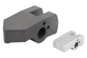
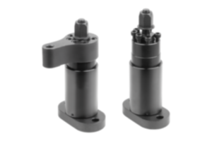
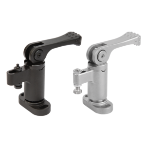
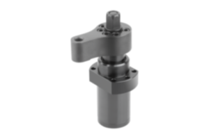
Floating clamp with separate clamping and interlocking mild steel nitruré, bruni et rectifié 04421-100812
- Simultaneous clamping and supporting of overhanging clamping points on components
- Prevents vibrations and bending
- Height infinitely adjustable
- Low-warp clamping
- Fixed support possible
Unité de vente
1 174,39 CHF
hors TVA
Ajouté à votre panier
Désignation
Système de bridage réglable
Modèle 1
Avec serrage et blocage séparés
Forme
A
Matériau
du corps de base
acier de cémentation
Surface
du corps de base
nitruré, bruni et rectifié
Matériau
des composants
aluminium
Surface
des composants
anodisé
Coloris
des composants
bleu
Course d’approche
10 mm
Force d’appui
à max.
30 Nm (kN)
8
Force d’appui
à min.
15 Nm (kN)
2
course de serrage max.
12
Description
Material
Base body and jaws steel.
Housing aluminium.
Housing aluminium.
Version
Body nitrided, black oxidised and ground.
Jaws nitrided and black oxidised.
Housing anodised blue.
Jaws nitrided and black oxidised.
Housing anodised blue.
Note
The floating clamp is used to clamp and support overhanging points on thin walled, sensitive and pliable components. It prevents vibrations and bending during machining.
Method of operation
1. Push the floating clamp down.
2. Pivot the jaws in. The lower jaw contacts the workpiece with a light spring force.
3. Tighten the AF 18 hexagon nut with max. 15 Nm torque. The jaws clamp the workpiece, the clamp is still floating.
4. Tighten the AF 10 hexagon nut with max. 10 Nm torque. The clamping process is completed.
5. Reverse the process to release.
2. Pivot the jaws in. The lower jaw contacts the workpiece with a light spring force.
3. Tighten the AF 18 hexagon nut with max. 15 Nm torque. The jaws clamp the workpiece, the clamp is still floating.
4. Tighten the AF 10 hexagon nut with max. 10 Nm torque. The clamping process is completed.
5. Reverse the process to release.
Assembly
Form A:
Fasten the floating clamp to the fixture with the M12 screw.
Adjust the height stop and the swivel range using the blue sleeve and lock with the 3x2.5 mm grub screws. When setting the height leave generous clearance above.
For safe operation the M12 tapped hole must always be closed.
For specific clamping applications the standard jaws can be altered or replaced.
Form B:
Fasten the floating clamp with M6 fastening holes to a fixture.
Adjust the height stop and pivot range using the blue adjusting sleeve and clamp with grub screws (4x AF 2.5). When setting the height limit, allow ample play at the top.
For specific clamping situations, the standard jaw plates can be modified or replaced.
Fasten the floating clamp to the fixture with the M12 screw.
Adjust the height stop and the swivel range using the blue sleeve and lock with the 3x2.5 mm grub screws. When setting the height leave generous clearance above.
For safe operation the M12 tapped hole must always be closed.
For specific clamping applications the standard jaws can be altered or replaced.
Form B:
Fasten the floating clamp with M6 fastening holes to a fixture.
Adjust the height stop and pivot range using the blue adjusting sleeve and clamp with grub screws (4x AF 2.5). When setting the height limit, allow ample play at the top.
For specific clamping situations, the standard jaw plates can be modified or replaced.
Remarque importante concernant le téléchargement des modèles CAO
Pour pouvoir télécharger nos modèles CAO, vous devez d’abord connecter. Si vous n’avez pas encore créé de compte, inscrivez-vous en cliquant sur « Mon compte » (à droite de l’écran) et suivez les instructions.
D'autres clients ont également acheté