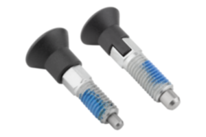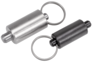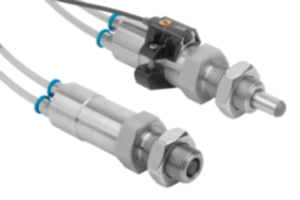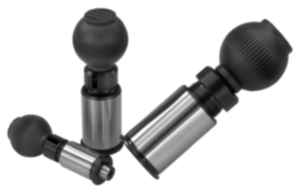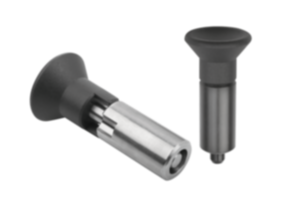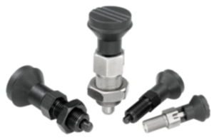


Actuating element with mushroom knob stainless steel bright 03096-10-1442010
- Actuation possible in inaccessible assembly spaces
- Ergonomically optimised actuating position possible
- Actuation possible even when safety distances are required
- Easy replacement of wear parts
- Flexible connection of an actuating element
Unità di vendita
43,99 CHF
Aggiunto al carrello
Denominazione
Elemento di azionamento
Versione 1
con pomello a fungo
Forma
D
Tipo di forma
con incavo d'arresto, con controdado
Materiale
Corpo base
acciaio inox
Superficie
corpo base
grezzo
Materiale
Componente
resina termoplastica
Colore
Componente
grigio nerastro RAL 7021
D1=Filettatura
M20x1,5
L=Longueur
76
Chiave in acciaio
1.4305
Colore
coperchio
grigio nerastro RAL 7021
Controdado
con controdado
Corsa
S
10
D
Filettatura interna
M6
D2
33
Dimensioni
4
L1
28
L2
12
L3
25
SW1
22
SW2
30
~ CONFLICT MINERALS 3TG status
no intentional 3TG
~ CP65 substance 2 cancer
nickel (metallic)
~ PFAS free?
not yet identified
~ REACH SVHC-free?
yes
~ RoHS conformity
yes, without exemption
~ TSCA 6(H) conformity
yes
Descrizione
Product description
Indexing plungers are used where any change in locking position due to lateral forces should be prevented.
A new indexed position can be only be moved to after the pin has been manually retracted.
Indexing plungers with remote actuation are used where inaccessible assembly spaces are making it difficult to operate, or where remote actuation is required for ergonomic or safety reasons.
The indexing plunger is connected to the operator side by a Bowden cable. The combination of indexing plunger and actuating element forms a complete system which can be used for many types of application. Form D should be used for applications where the indexing pin should remain disengaged for an extended period and be prevented from springing back.
Material
Indexing plunger:
Threaded sleeve 1.4305.
Indexing pin 1.4034.
Actuating element 1.4305.
Mushroom grip thermoplastic
Wire cable 1.4401.
Traction sleeve steel wire with plastic sleeving inside and outside.
End sleeves, set screws and screw nipples brass.
Version
Threaded sleeve bright.
Indexing pin hardened and ground, bright.
Bowden cable casing black.
Mushroom grip black grey RAL7021 thermoplastic.
Indexing pin hardened and ground, bright.
Bowden cable casing black.
Mushroom grip black grey RAL7021 thermoplastic.
Note for ordering
Indexing plungers with remote actuation and actuating element must be ordered separately.
Note
The supplied screw nipple (Ø5 x 7 mm) can be used as an alternative to the actuating element to integrate a customised actuating element into the system.
Different lengths of the Bowden cable are available.
The Bowden cable can be shortened as required during installation to ensure an exact fit in the application concerned.
Corrosion protection is achieved by selecting a suitable material and surface treatment. The wire cable or cable sheath can be easily replaced if required.
Note the following points when installing Bowden cables:
The length of the free end of the cable can change due to layout angle, bend radius and load factors. Therefore, the length of the opposing bracket (cable sheath) must be adjusted using the enclosed set screw after the Bowden cable has been laid. The set screw is also used to set the tension in the Bowden cable system.
During installation, take particular care to ensure that the bend radius is not less than the minimum value, which in this case is R = 65 mm. A radius which is too small can lead to increased wear and higher friction.
Briefly bending less than the min. bending radius during installation should also be avoided, as this can damage the cable sheath. The sheath is also only designed to absorb compressive forces. If it is pulled too hard, the internal spiral will stretch and be permanently damaged.
Scope of delivery
Actuating element with plastic cover.
On request
Special versions.
Drawing reference
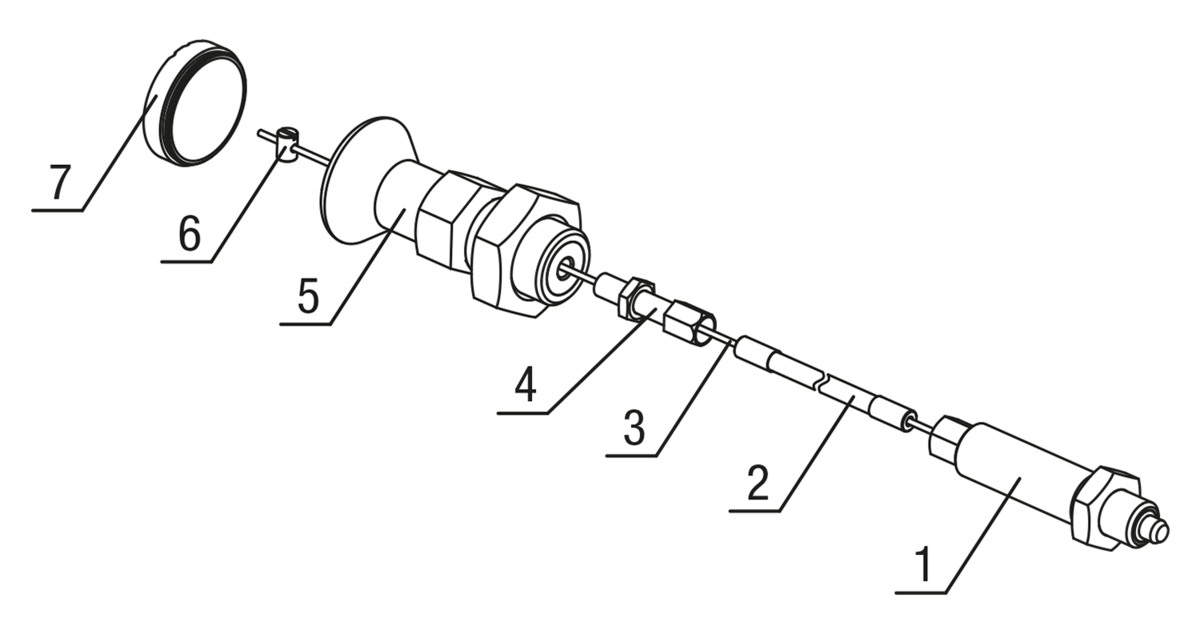
1) Indexing plunger
2) Bowden cable casing
3) Bowden cable
4) Adjusting screw
5) Actuating element
6) Screw nipple
7) Cover
Form D: lockout type, with locknut
2) Bowden cable casing
3) Bowden cable
4) Adjusting screw
5) Actuating element
6) Screw nipple
7) Cover
Form D: lockout type, with locknut
Accessory
Hex nuts 07212.
Mounting brackets 03099.
Spacer rings 03089.
Positioning bushes 03099-50.
Actuating elements 03096-10-12420.
Bowden cable 03096-14.
Wire cables 03096-15.
Tension sleeves 03096-20.
End sleeves 03096-25.
Setscrews 03096-30.
Screw nipples 03096-35.
Mounting brackets 03099.
Spacer rings 03089.
Positioning bushes 03099-50.
Actuating elements 03096-10-12420.
Bowden cable 03096-14.
Wire cables 03096-15.
Tension sleeves 03096-20.
End sleeves 03096-25.
Setscrews 03096-30.
Screw nipples 03096-35.
Nota importante sul download dei modelli CAD
Per poter scaricare i nostri modelli CAD, occorre effettuare il login. Se non è stato ancora creato un account, si prega di registrarsi alla voce "Il mio account" (lato destro dello schermo) e di seguire le istruzioni.
Other customers also bought