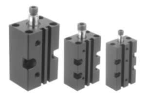
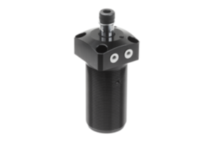
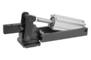
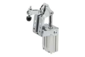
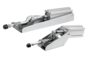
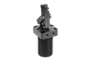
Pneumatic clamp with vertical cylinder attachment QT steel 05360-06
- Pneumatic clamps are used as assembly and workholding fixtures
- Application sectors: machine construction, metal processing, woodworking, plastics industry
- Double action
- Automatable
Sales unit
1 339,98 CHF
plus sales tax
Added to your shopping cart
Designation
Pneumatic clamp
Version 1
with vertical cylinder attachment
Main
material
QT steel
H5=Total height
195
A
20
B
91
D
13
E
60
F
22
F1
kN
12
F2
kN
18
F3
kN
2,5
F4
kN
3,5
F5
kN
1
G
83
H
69
I
40
K
12
L
32
M
107
M1
100
N
137
O
M16x1,5
Q
8,2
R
G1/4
S
54
T
48
U
221
V
101
VL
1,8
W
16
X
50
Y
87
Z
26
total length
386
~ CONFLICT MINERALS 3TG status
no intentional 3TG
~ CP65 substance 2 cancer
soots, tars, and mineral oils
~ PFAS free?
no
~ PFAS substance/s
PTFE
~ REACH SVHC-free?
yes
~ RoHS conformity
yes, without exemption
~ TSCA 6(H) conformity
yes
Description
Material
Carbon steel.
Version
Black oxidised.
Note
The clamps 05350 and 05360 are suitable for fitting in special machines and transfer machines. The tempered and ground bearing pins that run in Teflon bearings make them maintenance-free. The heavy-duty design and the double-acting pneumatic cylinder guarantee a long life.
The fastening screws for the hinges are secured with LOCTITE.
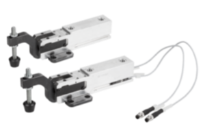
The magnetic piston is prepared for electric end position feedback.
VL = compressed air consumption per complete cycle in dm³ at 6 bar.
Clamping and retaining forces
The selection of the correct clamp size is dependant on the force (see table). It is distinguish between retaining force F1 or F2 and clamping force F3 or F4.
The clamping force F3 and F4 is the force exerted by the clamping arm on the part to be machined when the clamp is closed.
The retaining force F1 and F2 is the force with which the closed clamping arm opposes the machining forces occurring on the part to be machined and which it resists with no permanent deformation. It is greater than the clamping force because the dead point of the lever has to be overcome with the clamp closed when being pushed back.
On request
Clamps without cylinder.
Drawing reference
Y = cylinder travel
Important note on downloading CAD models
In order to download our CAD models, you must log in first. If you have not created an account yet, please register under "My Account" (right side of the screen) and follow the instructions.
Other customers also bought